


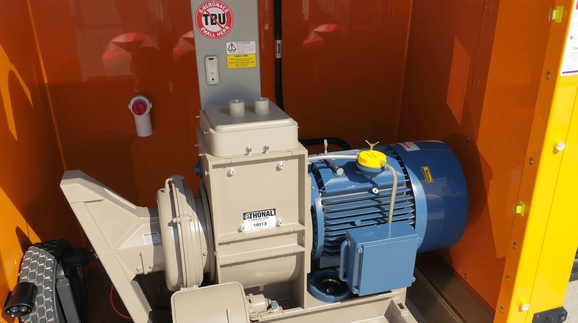
A single-shaft shredder rarely loses performance for only one reason. Low throughput, repeated overload reversals, uneven output, vibration and hot hydraulic oil can all originate in the feed system, cutting chamber or drive system. Effective troubleshooting therefore starts with evidence: record the alarm, motor load, material condition, output size and the exact point in the cycle where performance changes.
This guide provides a practical diagnostic sequence for industrial single-shaft shredders. It does not replace the machine manual, site safety procedure or work by qualified electrical, hydraulic and mechanical personnel. For a visual explanation of the systems mentioned below, see our single-shaft shredder components guide.
Safety Before Troubleshooting
Stopping the motor is not the same as isolating the machine. A shredder may retain electrical, hydraulic, pneumatic, gravitational and mechanical energy. Before opening the cutting chamber, screen housing or drive guard, follow the site’s written lockout/tagout procedure, release or restrain stored energy, and verify a zero-energy state. OSHA publishes guidance on control of hazardous energy and machine guarding.
- Never enter the hopper or cutting chamber until all energy sources are isolated and verified.
- Never bypass a guard switch, screen interlock, emergency stop or overload protection to keep production running.
- Block or support raised covers, screen baskets and other heavy components with rated devices.
- Treat blades, counter knives and trapped material as sharp, unstable loads.
- Escalate electrical, PLC, hydraulic-pressure and bearing work to qualified personnel.
Fast Single-Shaft Shredder Diagnostic Map
| Symptom | Likely Areas | First Checks | Stop Condition |
|---|---|---|---|
| Throughput falls but the machine keeps running | Feed, knives, counter knife, screen | Feed consistency, knife edges, clearance, screen blockage | Blade contact, severe heat or abnormal current |
| Frequent overload reversals or trips | Foreign objects, bridging, cutting load, drive | Feed size, contaminants, rotor area, alarm history | Knocking, smoke, repeated instantaneous trips |
| Material will not bite | Pusher, rotor profile, wrapping, knife condition | Pusher travel, guides, material behavior, rotor buildup | Hydraulic leak, damaged guide or unsafe bridging |
| Oversized or inconsistent output | Screen, knives, counter knife, bypass path | Screen damage, openings, edge condition, chamber wear | Broken screen or loose internal part |
| New vibration or impact noise | Knife installation, buildup, bearings, alignment | Recent service work, fasteners, pockets, rotor, bearings | Any sudden or increasing vibration |
| Hydraulic oil runs hot | Oil level, filter, cooler, valve, pusher load | Oil condition, temperature trend, cooler airflow, leakage | Burnt smell, foaming, severe leak or pressure instability |
Collect Baseline Data Before Changing Settings
Changing several parameters at once hides the root cause. Record a short baseline using normal feedstock and the approved operating recipe, then change one variable at a time.
- Alarm code, timestamp and operating step when the event occurred
- Motor current or load trend before and during the event
- Hydraulic oil temperature, pusher movement and any pressure alarm
- Material type, bulk density, moisture, piece size and contamination
- Knife-edge condition, counter-knife condition and last service date
- Screen opening, screen condition and target output size
- Photos or video of feed behavior and produced material, taken from a safe position
- Any recent blade, screen, bearing, motor, gearbox or control work
This record distinguishes a machine fault from a feedstock change. It also gives the manufacturer enough information to provide useful support instead of requesting the same checks again.
Problem 1: Low Throughput While the Shredder Still Runs
Low throughput is often a cutting or feeding problem rather than insufficient motor power. Compare the current feedstock and output with a known good production run.
- Check the feed. Large bundles, slippery film, hollow parts and low-bulk-density material may bridge or move away from the rotor.
- Observe the pusher cycle. Confirm that the ram travels smoothly and applies material consistently instead of stalling, chattering or retracting too early.
- Inspect the cutting edges. Rounded or chipped rotor knives require more force and may rub rather than shear.
- Inspect the counter knife and clearance. A worn fixed knife, contaminated mounting surface or excessive gap can reduce bite and increase recirculation.
- Inspect the screen. Melted plastic, labels, film or packed fines can blind open area and trap material in the chamber.
- Check downstream equipment. A stopped conveyor, full bin or blocked discharge can make the shredder appear underproductive.
If blade wear is confirmed, use the machine-specific service procedure. Our guides to shredder blade selection and blade replacement and maintenance explain the related checks.
Problem 2: Frequent Overload Reversals or Motor Trips
Automatic reversal protects the cutting and drive systems; it is not a defect by itself. Repeated reversals indicate that the rotor cannot complete the cut under the current conditions.
- Foreign objects: metal, stone or unapproved thick sections can cause a sudden load spike.
- Oversized feed: a piece may be acceptable material but too large or awkward for the hopper and rotor geometry.
- Wrapped material: film, straps and textile can accumulate at rotor ends or around the shaft.
- Dull cutting system: worn knives and incorrect clearance increase motor load during every cut.
- Aggressive pusher command: the ram may force material faster than the rotor can process it.
- Drive or electrical problem: poor connections, incorrect protection settings, cooling loss, coupling slip, gearbox damage or motor faults require qualified diagnosis.
Do not simply raise overload limits or bypass automatic reversal. Compare the protection settings with the approved machine documentation and investigate the mechanical load first.
Problem 3: Material Will Not Bite or the Pusher Stalls
When material repeatedly lifts, spins or slides across the rotor, inspect both the feedstock and the pusher system. A hydraulic ram should load the rotor consistently without crushing material into an immovable bridge.
- Remove bridging only under full energy isolation using the approved method.
- Check pusher guides, wear strips, cylinder mounts and the chamber floor for damage or trapped fragments.
- Look for hydraulic leaks, aerated oil, a blocked filter or unstable pusher motion.
- Inspect rotor knife edges and pockets for plastic buildup that changes the bite profile.
- For film, raffia or textile, inspect rotor ends and seals for wrapping.
- Confirm that the feed recipe and pusher control suit the material rather than copying settings from rigid scrap.
Problem 4: Output Is Oversized, Inconsistent or Too Fine
A single-shaft shredder normally retains material until it can pass through the screen. Output drift therefore points first to the screen and cutting relationship.
- Oversized pieces: inspect for a cracked, loose, worn or incorrectly installed screen; also check bypass gaps and chamber wear.
- Long strips: inspect knife sharpness, counter-knife condition, cutting clearance and the behavior of flexible feedstock.
- Excess fines: check whether material remains in the chamber too long because of a blinded screen, dull blades or an unnecessarily small screen opening.
- Heat or melting: look for rubbing, overloaded recirculation, insufficient discharge and unsuitable operating conditions.
Do not choose a screen only by nominal hole size. Target output, downstream granulator feed, bulk density and acceptable fines all affect the correct selection.
Problem 5: Vibration or Noise After Knife Service
Stop the shredder if vibration appears suddenly after blades were rotated or replaced. Continuing to run can damage knife pockets, the counter knife, bearings, rotor or gearbox.
- Confirm every knife is the correct geometry, thickness and orientation.
- Inspect knife pockets for debris, raised damage and incomplete seating.
- Verify approved fasteners, locking method, torque and tightening sequence.
- Check counter-knife clearance through the required rotor positions.
- Inspect the screen and internal guards for contact marks.
- Remove uneven material buildup from the rotor using the approved procedure.
- If vibration remains, have qualified personnel inspect bearing condition, rotor runout, coupling alignment and gearbox mounts.
Problem 6: Hydraulic Oil Runs Hot or the Pusher Chatters
High oil temperature reduces viscosity and can accelerate seal, valve and pump wear. Check the temperature trend rather than judging by touch.
- Verify oil level and the approved oil grade.
- Inspect the oil for foam, cloudiness, contamination or a burnt smell.
- Check filter indicators and maintenance records.
- Clean cooler surfaces and confirm fan or water flow where fitted.
- Inspect hoses, fittings, cylinder seals and the power unit for external leakage.
- Check whether the pusher is continuously working against a bridge or mechanical obstruction.
- Have a qualified hydraulic technician evaluate relief, directional and flow-control valves if heat or unstable movement continues.
Problem 7: Bearing, Gearbox or Drive Warning Signs
Rising bearing temperature, lubricant leakage, metallic noise, coupling debris or increasing vibration should be investigated before failure. Compare both sides of the rotor and review trends under similar loads. A damaged seal may allow fine plastic or washing-line moisture to enter a bearing area, while loose mounts or misalignment can overload the gearbox and coupling.
Do not diagnose internal bearing or gearbox condition solely from external temperature. Use the manufacturer’s inspection method and qualified vibration, alignment or lubricant analysis where appropriate.
Controlled Restart Checklist
- Confirm the root cause has been corrected and all tools and loose parts are removed.
- Verify the rotor, knives, counter knife, screen, fasteners and discharge path.
- Reinstall guards, access covers and working safety interlocks.
- Clear personnel and remove locks according to the site procedure.
- Run the approved no-load test and monitor noise, vibration, current and leakage.
- Introduce a small amount of known feedstock and compare the result with baseline data.
- Stop immediately if the original symptom returns or a new symptom appears.
- Record the repair, parts, settings and test result in the maintenance history.
When to Stop and Contact Technical Support
Escalate the issue when there is a cracked rotor or frame, damaged knife pocket, repeated unexplained electrical trip, internal gearbox noise, significant bearing play, unstable hydraulic pressure, failed safety device or recurring problem after the basic cause has been corrected. Send the machine model and serial number, control alarm history, current trend, feedstock details, screen specification, service history and clear photos.
Machine configuration also affects fault patterns. Compare our single-shaft shredder with drawer, rigid-plastic single-shaft shredder and film and raffia single-shaft shredder when evaluating whether the existing machine matches the application.
Frequently Asked Questions
Why does a single-shaft shredder keep reversing?
Repeated reversal usually means the rotor cannot complete the cut. Common causes include foreign objects, oversized feed, bridging, wrapped material, dull knives, incorrect clearance or an overly aggressive pusher command. Treat reversal as a protective signal and investigate the load rather than disabling it.
What causes low throughput even when the motor is running normally?
Check inconsistent feeding, pusher travel, rounded knife edges, counter-knife clearance, screen blockage and downstream discharge. A feedstock change can reduce production without creating an obvious motor alarm.
Why is the shredded output suddenly too large?
Inspect the screen for cracks, loose sections, wear or incorrect installation. Also check for bypass gaps, worn knives, a damaged counter knife and excessive cutting clearance. Stop the machine if a screen or internal part is loose.
What should I check when hydraulic oil gets hot?
Verify oil level and grade, filter condition, cooler airflow or water flow, external leakage and whether the pusher is working continuously against an obstruction. Burnt odor, foaming or unstable pressure requires the machine to be stopped and assessed by qualified personnel.
Can I increase the overload setting to stop nuisance trips?
Do not raise protection limits without approval from the machine manufacturer or responsible engineer. Trips may indicate a mechanical obstruction, cutting-system wear, drive fault or unsafe feed condition. Increasing the limit can transfer damage to the motor, gearbox, rotor or blades.
What information should I send when requesting shredder support?
Provide the model and serial number, alarm history, motor-load trend, hydraulic temperature, feedstock and contamination details, screen specification, knife condition, recent service work, and safe photos or video of the feed and output.
Request Technical Support
Send the machine model, alarm record, feedstock details, current operating data and clear photos of the cutting chamber or output. Our team can help identify the next inspection step and determine whether parts or on-site service are required.
