


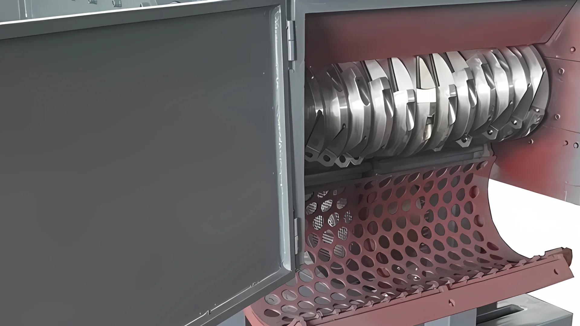
A single-shaft shredder is a coordinated system, not just a rotor with knives. The hopper presents material, a hydraulic pusher controls contact with the rotor, knives shear against a counter knife, a screen controls discharge size, and the drive and control systems protect the machine when cutting load rises. Component design therefore determines output consistency, energy demand, service access and suitability for a particular feedstock.
This guide explains the main components, how they work together and what buyers should compare. For operating faults and diagnostic steps, use our separate single-shaft shredder troubleshooting guide.
Single-Shaft Shredder Component Map
| Component | Main Function | Selection Impact | Common Maintenance Signal |
|---|---|---|---|
| Feed hopper and frame | Contains feed and supports cutting loads | Piece size, loading method, structural duty | Cracks, loose mounts, bridging or wear |
| Hydraulic pusher | Moves material toward the rotor | Feed consistency and overload behavior | Chatter, leakage, slow or uneven travel |
| Rotor and knife pockets | Carry cutters and transmit torque | Bite, throughput, impact resistance | Buildup, pocket damage, runout or vibration |
| Rotor knives and counter knife | Create the shearing action | Cut quality, energy use, wear life | Rounded edges, chips, heat or poor output |
| Screen | Retains material until it reaches discharge size | Output size, recirculation and throughput | Blinding, cracks, loose sections or wear |
| Drive train | Supplies and transfers rotor torque | Duty cycle, recovery from shock load | Heat, noise, leakage, slip or misalignment |
| Bearings and seals | Support the rotor and exclude contamination | Reliability in dusty or wet service | Temperature, vibration, play or lubricant loss |
| Controls and safety devices | Manage feed, overload and protected access | Automation, integration and operator protection | Alarm, sensor fault or failed interlock |
1. Feed Hopper and Machine Frame
The hopper receives loose material, bales, purgings or other approved feed and keeps operators separated from the cutting chamber. Its opening, wall angle and usable volume should match the longest and bulkiest pieces as well as the loading method. A hopper that is too small encourages bridging and repeated handling; an oversized hopper without suitable support can increase structural and loading risks.
The frame carries cyclic cutting, pusher and drive loads. Buyers should review material thickness, reinforcement around the cutting chamber, replaceable wear plates, foundation requirements and access for cleaning or repair. Frame cracks, loose anchor points and worn hopper surfaces are system problems, not cosmetic defects.
2. Hydraulic Pusher or Ram
The pusher moves material against the rotor so the knives can maintain a controlled bite. Depending on the design, it may be a horizontal ram, swing ram or drawer-style mechanism. Load-responsive control can advance, pause or retract the pusher according to motor load, reducing repeated overloads while maintaining feed pressure.
- Cylinder and hydraulic power unit: generate and control ram movement.
- Guides and wear strips: keep the pusher aligned under uneven loads.
- Floor and sealing arrangement: limit debris entry into guides and hydraulic areas.
- Position and load feedback: coordinate pusher travel with rotor demand.
Pusher speed alone does not determine throughput. An aggressive ram can create more overload reversals if the cutting system, screen or downstream discharge cannot keep up.
3. Rotor and Knife Pockets
The rotor transmits drive torque to the cutting edges. Diameter, working width, speed, knife arrangement and pocket design influence bite, torque demand and material movement across the chamber. Rotor profiles may be optimized for flexible feed, rigid parts, heavy purgings or mixed bulky waste.
Knife pockets must locate each cutter accurately and transfer impact without allowing movement. Debris beneath a knife, damaged threads or a raised pocket surface can create uneven loading and early cutter failure. Buyers should ask whether pockets are replaceable or repairable and how the rotor is accessed for inspection.
4. Rotor Knives
Rotor knives perform the moving part of the cut. Many single-shaft shredders use indexable square cutters with multiple usable edges, while other applications require special profiles or reinforced edge arrangements. Blade material, heat treatment, geometry and mounting must be matched to feedstock abrasiveness, impact risk and required output.
- Flexible film benefits from an arrangement that limits wrapping and maintains positive cutting.
- Rigid plastic and thick purgings require sufficient toughness as well as wear resistance.
- Contaminated feed may need upstream metal removal and a blade specification that tolerates occasional impact.
- Rotatable cutters reduce replacement frequency only when all edges, pockets and fasteners remain serviceable.
See the industrial shredder blade selection guide for a detailed comparison of blade steel, hardness and geometry.
5. Counter Knife or Stator Knife
The fixed counter knife provides the opposing edge against which rotor knives shear material. Its position and condition affect bite, motor load, heat and particle shape. Excessive clearance can create long strips and recirculation; insufficient or inconsistent clearance can cause contact as the rotor turns.
There is no universal clearance for every shredder. The correct range depends on the model, rotor runout, knife geometry and feedstock. Serviceability depends on accessible fasteners, clean mounting surfaces, approved shims or adjustment points and the ability to measure the gap through specified rotor positions.
6. Calibration Screen and Screen Basket
The screen retains material in the cutting chamber until it is small enough to pass through the openings. Screen opening, thickness, open area and shape affect both output distribution and throughput. A smaller opening usually increases recirculation; it does not automatically produce a better downstream result.
- Specify output for the next process, such as conveying, washing or granulation.
- Check whether the screen is sectional and can be changed without disturbing major assemblies.
- Review screen support and interlocking so a loose or open basket cannot expose the rotor.
- Plan for blinding when processing film, labels, wet feed or tacky material.
7. Drive Train: Motor, Gearbox and Coupling
The drive train converts electrical power into low-speed rotor torque. Common arrangements include an electric motor, reduction gearbox and coupling or belt system. The correct choice depends on peak cutting load, duty cycle, rotor inertia, overload strategy and maintenance access rather than motor power alone.
- Motor: must suit the supply, starting method, enclosure, cooling and operating duty.
- Gearbox: reduces speed and carries changing torque; lubrication, mounting and shock protection affect life.
- Coupling or belt: transfers power and may absorb or isolate some shock, but alignment and condition remain critical.
- Torque or load protection: works with automatic reversal to prevent a jam from becoming a major mechanical failure.
8. Bearings, Seals and Rotor Supports
Bearings support the rotor under radial, axial and impact loads. Seal design is especially important around abrasive dust, wet washing-line feed and wrapping material. External or protected bearing placement, labyrinth arrangements, replaceable sleeves and purge or lubrication provisions can reduce contamination risk.
Ask how bearings are inspected and replaced, whether the rotor must be removed, and which seals are included in the recommended spare-parts package. Temperature, vibration, lubricant leakage and shaft play are warning signs that should be trended rather than ignored.
9. Hydraulic Power Unit
The hydraulic power unit normally includes the reservoir, pump, motor, filter, valves, cooler and instrumentation used to operate the pusher. Oil cleanliness, stable temperature and correct valve operation determine whether the pusher moves smoothly and responds predictably to changing rotor load.
Compare filter access, cooling capacity, oil-level and temperature indication, hose routing, pressure-test points and spare seal availability. Hydraulic settings must follow the machine documentation; increasing pressure to overcome a mechanical bridge can damage the pusher or frame.
10. Electrical Controls, Sensors and Overload Logic
The control system coordinates rotor start, pusher movement, overload reversal, alarms and downstream equipment. A PLC-based system can use motor load and position feedback to prevent the pusher from forcing material faster than the rotor can cut.
- Motor protection and approved start or variable-speed control
- Pusher position, pressure or load feedback
- Rotor speed or jam detection where fitted
- Screen, door and guard interlocks
- Emergency-stop circuit and reset logic
- Alarm history and accessible diagnostic information
- Interfaces for conveyors, metal detectors, granulators and central controls
11. Guards, Access Doors and Safety Interlocks
Guards and interlocks are functional machine components. They limit access to the rotor, drive and moving pusher, and they must remain effective after maintenance. A screen-change door or chamber cover should be mechanically secured during service and interlocked during operation. Emergency stops do not replace energy isolation for maintenance.
During procurement, request the applicable conformity documentation, electrical drawings, safety-circuit description, lockout points, training scope and maintenance access procedure for the destination market.
How the Components Work Together
- Material enters the enclosed hopper using the approved loading method.
- The pusher advances material toward the rotor.
- Rotor knives draw material against the counter knife and shear it.
- Material that is still too large remains above the screen and returns to the cutting zone.
- Acceptable pieces pass through the screen to the discharge conveyor or downstream process.
- If cutting load exceeds the control threshold, the pusher pauses or retracts and the rotor may reverse according to the programmed protection sequence.
- Interlocks stop hazardous motion when a protected access point is opened.
A bottleneck in any one component changes the whole cycle. For example, a blocked screen increases recirculation, which raises cutting load and may trigger more reversals even though the motor and pusher are operating correctly.
Matching Components to Feedstock
| Feedstock | Component Priorities | Questions to Resolve |
|---|---|---|
| Film, raffia and woven bags | Positive feed, anti-wrapping rotor detail, rotor-end sealing, screen behavior | How will light material be loaded, and what prevents wrapping? |
| Rigid bottles, crates and molded parts | Hopper opening, knife arrangement, screen, metal-contamination control | What is the largest part and desired downstream size? |
| Thick purgings and head waste | Rotor torque, knife toughness, pusher structure, drive shock protection | What are maximum piece dimensions and hidden inserts? |
| Pipe and profiles | Feed geometry, anti-roll features, hopper length, controlled bite | Can full lengths be loaded safely, or is pre-cutting required? |
| Wet or contaminated plastic | Seals, bearings, corrosion protection, drainage and cleanability | What moisture, fines and contaminants reach the machine? |
Application-specific examples include our rigid-plastic shredder and film and raffia shredder. The broader plastic shredder working principle explains where single-shaft machines fit among other shredder types.
Component and Spare-Parts Checklist for Buyers
- Rotor drawing, knife layout, knife material and usable edge count
- Counter-knife adjustment method and specified clearance procedure
- Available screen openings, open area and screen-change method
- Pusher style, guide arrangement and control response to motor load
- Motor, gearbox, coupling and overload-protection details
- Bearing and seal arrangement for the actual environment
- Hydraulic filtration, cooling and diagnostic points
- PLC, alarm history, electrical drawings and line-integration signals
- Guarding, access interlocks, emergency stops and lockout points
- Routine spare package: rotor knives, counter knives, screens, fasteners, seals, filters and sensors
- Wear-part drawings, recommended tools, manuals and training
- Remote support requirements and expected availability of critical parts
Service access can matter as much as rated capacity. A component that takes hours to reach or requires unavailable lifting equipment can dominate real downtime. Review our blade replacement and maintenance guide when evaluating access and tooling.
Frequently Asked Questions
The main systems are the hopper and frame, hydraulic pusher, rotor, rotor knives, counter knife, calibration screen, motor and gearbox, bearings and seals, hydraulic power unit, controls, sensors, guards and safety interlocks.
The screen is the primary sizing component because material remains in the chamber until it can pass through an opening. Knife condition, counter-knife clearance, feedstock behavior and chamber wear also affect the actual particle distribution.
The pusher keeps bulky or low-density material in controlled contact with the rotor. Load-responsive control can pause or retract the ram when cutting demand rises, improving feed consistency without continuously overloading the rotor.
Many machines use square indexable knives with multiple usable edges, but designs vary. A knife should only be rotated when it remains within the manufacturer’s dimensional limit and has no cracks, deformation, pocket damage or unsuitable wear.
A practical package often includes rotor knives, counter knives, approved fasteners, one or more screens, hydraulic filters and seals, critical sensors and other model-specific wear parts. The final list should follow feedstock, duty cycle and local lead times.
Request drawings and specifications for the rotor, knives, counter knife, screen, pusher, drive, bearings, hydraulics and controls. Compare service access, protection logic, safety documentation, spare availability and a material test instead of relying only on motor power or catalog throughput.
Request a Component Review or Quotation
Send the feedstock, maximum piece size, contamination, target output, required throughput and downstream process. Our team can recommend a suitable rotor, knife, screen, pusher and drive configuration for review.
